
Hot sale Factory 86mm Hybrid Stepper Motor - stepper motor driver-DM542A – Longs Motor Detail:
Introduction:
DM542A is a type of two-phase hybrid stepping motor driver, The drive voltage of which is from 18VDC to 50VDC. It is designed for use with 2-phase hybrid stepper motor of all kinds with 42mm to 86mm outside diameter and less than 4.0A phase current. This circuit that it adopts is smiliar to the circuit of servo control which enables the motor run smoothly almost without noise and vibration. Hording torque when DM542A run under high speed is also significantly higher than the other two-phase driver, whats more, the positioning accuracy is also higher. It is widely used in middle and big size numerical control devices such as curving machine, CNC machine, computer embroider machine, packing machines and so on.
Features:
l High performance, low price
l Average current control, 2-phase sinusoidal output current drive
l Supply voltage from 18VDC to 50VDC
l Opto-isolated signal I/O
l Overvoltage, under voltage, overcorrect, phase short circuit protection
l 15 channels subdivision and automatic idle-current reduction
l 8 channels output phase current setting
l Offline command input terminal
l Motor torque is related with speed, but not related with step/revolution
l High start speed
l High hording torque under high speed
Electrical specification:
| Input voltage | 18-50VDC |
| Input current | < 4A |
| Output current | 1.0A~4.2A |
| Consumption | Consumption:80W; Internal Insurance:6A |
| Temperature | Working Temperature -10~45℃;Stocking temperature -40℃~70℃ |
| Humidity | Not condensation, no water droplets |
| gas | Prohibition of combustible gases and conductive dust |
| weight | 200G |
- Pins assignments and description:
1) Connector Pins Configurations
| Pin Function | Details |
| PUL +,PUL- | Pulse signal, PUL+ is the positive end of pulses input pinPUL- is the negative end of pulse input pin
|
| DIR+,DIR- | DIR signal: DIR+ is the positive end of direction input pinDIR- is the negative end of direction input pin |
| ENBL+ | Enable signal: ENBL+ is the positive end of direction input pin. This signal is used for enabling/disabling the driver. High level for enabling the driver and low level for disabling the driver. |
| ENBL- | ENBL- is the negative end of direction input pin. Usually left unconnected (enabled) |
2) Pins wiring diagram:
PC’s control signals can be active in high and low electrical level. When the high electrical level is active, all control negative signals will be connected together to GND. When low electrical level is active, all control positive signals will be connected together to public port. Now give two examples( Open collector &PNP), please check them:
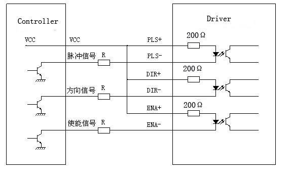
Fig 1. Input port circuit (Yang connection)
PC open connector output

Fig. 2 Input port circuit ( Yin connection)
PC PNP output

Note: When VCC=5V, R=0
When VCC=12V, R=1K, >1/8W
When VCC=24V, R=2K,>1/8W
R must connect in the control signal part .
3.Function choice ( Using DIP pins to achieve this function)
1) Micro step resolution is set by SW 5,6,7,8 of the DIP switch as shown in the following table:
|
SW5 |
OFF |
ON |
OFF |
ON |
OFF |
ON |
OFF |
ON |
OFF |
ON |
OFF |
ON |
OFF |
ON |
OFF |
|
SW6 |
ON |
OFF |
OFF |
ON |
ON |
OFF |
OFF |
ON |
ON |
OFF |
OFF |
ON |
ON |
OFF |
OFF |
|
SW7 |
ON |
ON |
ON |
OFF |
OFF |
OFF |
OFF |
ON |
ON |
ON |
ON |
OFF |
OFF |
OFF |
OFF |
|
SW8 |
ON |
ON |
ON |
ON |
ON |
ON |
ON |
OFF |
OFF |
OFF |
OFF |
OFF |
OFF |
OFF |
OFF |
|
PULSE/REV |
400 |
800 |
1600 |
3200 |
6400 |
12800 |
25600 |
1000 |
2000 |
4000 |
5000 |
8000 |
10000 |
20000 |
25000 |
2) Standstill current setting
SW4 is used for this purpose. OFF meaning that the standstill current is set to be half of the selected dynamic current and ON meaning that standstill is set to be the same as the selected dynamic current.
3) Output current setting:
The first three bits (SW 1, 2, 3)of the DIP switch are used to set the dynamic current. Select a setting
Closest to your motor’s required current
|
Output current (A) |
||||
|
SW1 |
SW2 |
SW3 |
PEAK |
RMS |
|
ON |
ON |
ON |
1.00 |
0.71 |
|
OFF |
ON |
ON |
1.46 |
1.04 |
|
ON |
OFF |
ON |
1.91 |
1.36 |
|
OFF |
OFF |
ON |
2.37 |
1.69 |
|
ON |
ON |
OFF |
2.84 |
2.03 |
|
OFF |
ON |
OFF |
3.31 |
2.36 |
|
ON |
OFF |
OFF |
3.76 |
2.69 |
|
OFF |
OFF |
OFF |
4.20 |
3.00 |
4) Semi-flow function:
Semi-flow function is that there is not step pulse after 500 ms, the driver output current automatically reduced to 70% of rated output current, which is used to prevent motor heat.
4. Pins of motor & power:
| Motor and power pins |
1 |
A+ |
Motors wiring | |
|
2 |
A- |
|||
|
3 |
B+ |
|||
|
4 |
B- |
|||
|
5,6 |
DC+ DC- |
Power supply | Power supply :DC18-50VDC |
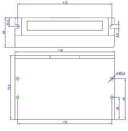
5. Mechanical Specification:
To have 20mm of space around, cannot be placed next to other heating devices. Whats more, avoid dust, oil mist, corrosive gas, heavy humidity and high vibration
6. Adjustment of troubleshooting
1) , the status on light’s indication
PWR: green, normal work light.
ALM: red, failure light, the motor with phase short-circuit, overvoltage and under-voltage protection.
2) Troubles
| Alarm indicator | Reasons | Measures |
| LED off turn | Wrong connection for power | Check wiring of power |
| Low-voltages for power | Enlarge voltage of power | |
| Motor doesn’t run, without holding torque | Wrong connection of stepper motor | Correct its wiring |
| RESET signal is effective when offline | Make RESET ineffective | |
| Motor doesn’t run, but maintains holding torque | Without input pulse signal | Adjust PMW & signal level |
| Motor runs wrong direction |
Wrong wires’ connection |
Change connection for any of 2 wires |
| Wrong input direction signal | Change direction setting | |
| Motor’s holding torque is too small | Too small relative to current setting | Correct rated current setting |
| Acceleration is too fast | Reduce the acceleration | |
| Motor stalls | Rule out mechanical failure | |
| Driver does not match with the motor | Change a suitable driver |
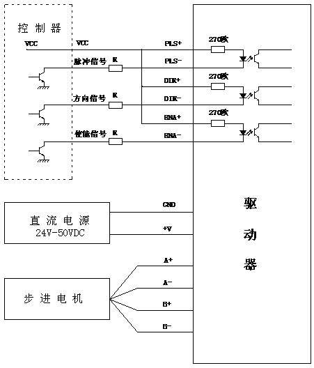
7. Driver wiring
A complete stepper motor control system should contain stepper drives, DC power supply and controller (pulse source). The following is a typical system wiring diagram
Product detail pictures:
Related Product Guide:
Finding Inexpensive Stepper Motors
CNC Stepper Motors
We also offer product sourcing and flight consolidation services. We've got our personal factory and sourcing office. We can easily present you with almost every style of merchandise linked to our merchandise range for Hot sale Factory 86mm Hybrid Stepper Motor - stepper motor driver-DM542A – Longs Motor, The product will supply to all over the world, such as: Armenia, South Africa, Sheffield, We are your reliable partner in the international markets of our products. We focus on providing service for our clients as a key element in strengthening our long-term relationships. The continual availability of high grade products in combination with our excellent pre- and after-sales service ensures strong competitiveness in an increasingly globalized market. We are willing to cooperate with business friends from at home and abroad, to create a great future. Welcome to Visit our factory. Looking forward to have win-win cooperation with you.
The company comply with the contract strict, a very reputable manufacturers, worthy a long-term cooperation.